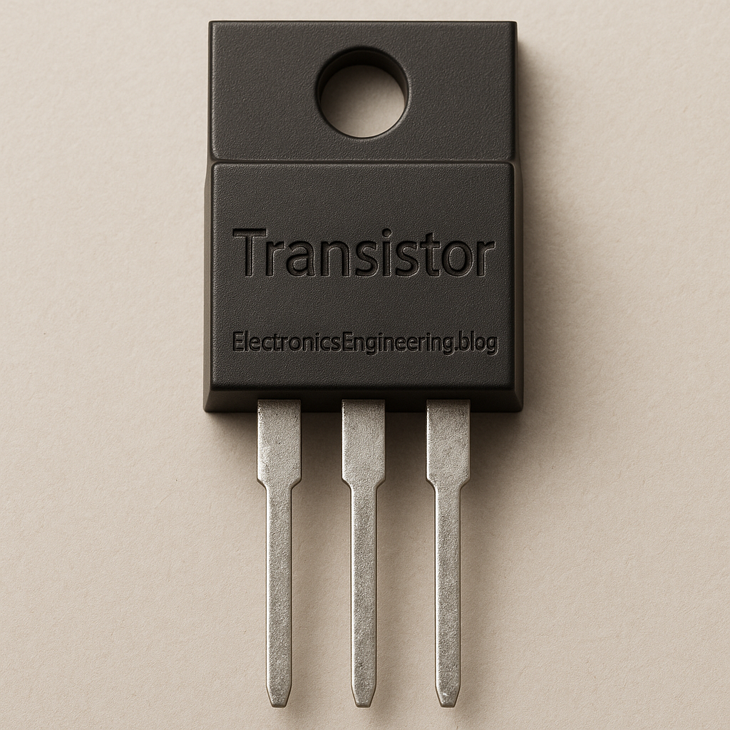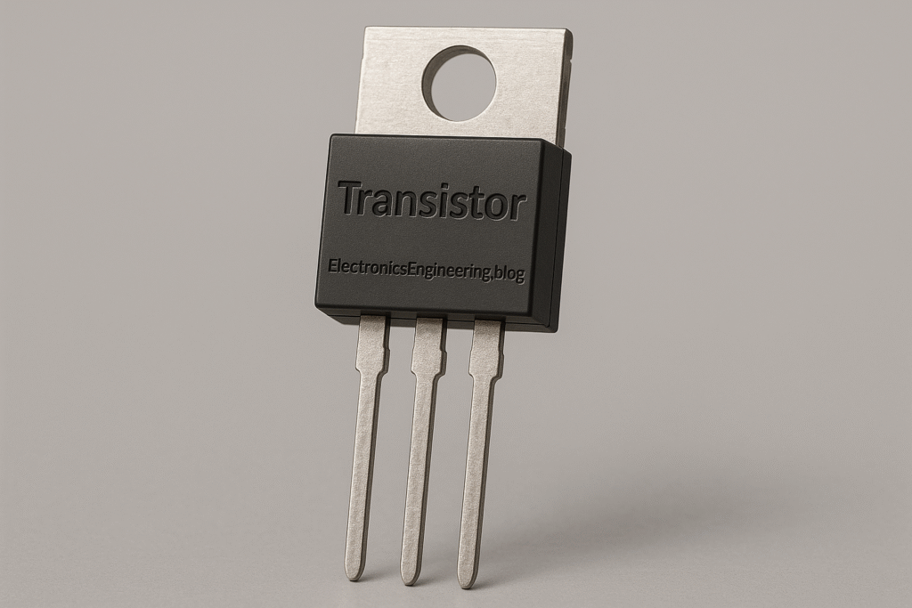
Micro Tutorial: Transistor
Practical Introduction
In the world of electronics, the transistor stands as a monumental achievement that has revolutionized how we design and build electronic devices. From the simplest radio to complex computers, transistors are the silent workhorses that make modern technology possible. My journey into electronics began with a simple curiosity about how these tiny components function, and it led me to a profound understanding of their significance. This micro-tutorial aims to provide you with a comprehensive overview of transistors, covering their fundamental principles, operational mechanics, applications, and more. Whether you are a beginner or an experienced enthusiast, this guide will enhance your understanding of transistors and their role in electronics.
Fundamentals
What is a Transistor?
A transistor is a semiconductor device that can amplify or switch electronic signals. It typically consists of three layers of a semiconductor material, which can either be N-type (doped with extra electrons) or P-type (doped with extra holes). The arrangement of these layers allows transistors to control current flow, making them essential for a variety of electronic applications.
Types of Transistors
Transistors can be broadly categorized into two main types: Bipolar Junction Transistors (BJT) and Field Effect Transistors (FET). Each type operates on different principles and is suited for various applications.
- Bipolar Junction Transistors (BJT):
- Comprised of three layers of semiconductor material (Emitter, Base, and Collector).
-
Operates by using a small current at the base to control a larger current flowing from the collector to the emitter.
-
Field Effect Transistors (FET):
- Consists of three terminals: Source, Gate, and Drain.
- Utilizes an electric field generated by voltage at the gate to control current flow between the source and drain.
Semiconductor Basics
To understand transistors, it’s essential to grasp the basics of semiconductors. Semiconductors are materials with electrical conductivity between that of conductors (like metals) and insulators (like glass). Silicon is the most commonly used semiconductor material in transistors due to its favorable electrical properties and abundance. Other materials, such as germanium and gallium arsenide, are also used in specific applications.
How It Works
Bipolar Junction Transistors (BJT)
BJTs operate by leveraging the interaction of charge carriers. When a small current flows into the base terminal, it allows a larger current to flow from the collector to the emitter. This property makes BJTs effective amplifiers.
Operation Modes
- Active Mode: The transistor allows current to flow from collector to emitter, controlled by the base current.
- Cut-off Mode: The transistor is off, and no current flows.
- Saturation Mode: The transistor is fully on, allowing maximum current to flow.
Field Effect Transistors (FET)
FETs control current flow using an electric field. When a voltage is applied to the gate, it alters the conductivity of the channel between the source and drain.
Operation Modes
- Enhancement Mode: The transistor is off when no voltage is applied to the gate, and it turns on when a positive voltage is applied.
- Depletion Mode: The transistor is normally on, and applying a voltage turns it off.
Comparison of BJT and FET
- Input Impedance: FETs generally have higher input impedance than BJTs, making them suitable for high-impedance applications.
- Power Consumption: FETs typically consume less power than BJTs, especially in digital circuits.
- Speed: FETs can switch faster than BJTs, making them ideal for high-speed applications.
Understanding the Current-Voltage Relationship
The current-voltage relationship in transistors is crucial for their operation. In BJTs, the relationship between the base current (I_B), collector current (I_C), and emitter current (I_E) is defined by the equation:
[ I_E = I_B + I_C ]
For FETs, the relationship is controlled by the voltage applied to the gate, which modulates the channel’s conductivity, allowing for precise control over the current flowing from the source to the drain.
Applications
Transistors are utilized in a myriad of applications across various fields, including:
-
Amplifiers: Transistors amplify weak signals, making them crucial in audio systems and communication devices. For example, in an audio amplifier, a small audio signal can be amplified to drive a speaker.
-
Switches: In digital circuits, transistors act as switches that turn current on and off, forming the basis of logic gates used in computers and digital devices.
-
Oscillators: Transistors can generate oscillating signals, which are essential in radio transmitters and receivers.
-
Voltage Regulation: Transistors are used in power supplies to regulate output voltage, ensuring devices receive stable power.
-
Signal Modulation: In communication systems, transistors modulate signals for transmission over various media.
-
Digital Logic Circuits: Transistors are the building blocks of digital logic circuits, enabling complex computations and data processing.
Switching Characteristics
Transistors can switch on and off rapidly, which is crucial for digital applications. The speed of switching is determined by several factors, including the transistor’s type and the circuit configuration.
Logic Gates
Transistors form the basis of logic gates, which perform basic logical operations. For example:
– AND Gate: Requires both inputs to be high for the output to be high.
– OR Gate: Requires at least one input to be high for the output to be high.
– NOT Gate: Inverts the input signal.
Amplification Characteristics
Transistors amplify signals by controlling a larger output current with a smaller input current. The amplification factor, often denoted by β (beta), indicates how much the transistor can increase the input signal. The relationship between input and output signals can be expressed as:
[ A_v = \frac{V_{out}}{V_{in}} ]
where ( A_v ) is the voltage gain, ( V_{out} ) is the output voltage, and ( V_{in} ) is the input voltage.
Key Parameters
Understanding the key parameters of transistors is crucial for effective application. Here are some critical parameters to consider:
- Current Gain (β): Indicates how much the base current is amplified in a BJT.
- Input Impedance: The resistance seen by the input signal; higher values are preferable for minimizing loading effects.
- Output Resistance: The resistance seen by the output signal; lower values are often better for power delivery.
- Maximum Collector Current (I_C): The maximum current a transistor can handle without damage.
- Breakdown Voltage (V_B): The maximum voltage the transistor can withstand without entering breakdown.
- Transition Frequency (f_T): The frequency at which the current gain drops to 1, indicating the maximum operating speed of the transistor.
Concrete Use Case
Let’s explore a concrete use case by designing a simple audio amplifier circuit using a BJT. This project is an excellent way for electronics enthusiasts to apply their knowledge of transistors in a practical scenario.
Designing the Audio Amplifier
To create an audio amplifier, gather the following components:
– A BJT (e.g., 2N3904)
– Resistors (for biasing and gain control)
– Capacitors (for input and output coupling)
– A power supply (e.g., 9V battery)
– A speaker (for output)
Circuit Configuration
The audio amplifier will be configured in a common-emitter configuration. In this setup:
– The input audio signal is applied to the base of the BJT.
– The output is taken from the collector.
– The emitter is connected to ground.
This configuration provides a significant voltage gain, making it suitable for amplifying audio signals.
Choosing Resistor Values
To bias the transistor correctly, select appropriate resistor values. A common approach is to use a voltage divider to provide a stable voltage to the base. For instance, resistors R1 and R2 can be chosen to set the base voltage at approximately 0.7V, which is the standard base-emitter voltage (V_BE) for silicon transistors.
Capacitive Coupling
Use coupling capacitors to isolate the input and output signals. The input coupling capacitor blocks any DC offset from the audio source, allowing only the AC signal to pass through. Similarly, place another capacitor at the output to prevent DC from reaching the speaker.
Power Supply Connection
For the power supply, a 9V battery or adapter is typically sufficient. Connect the positive terminal to the collector of the transistor and the emitter to ground.
Testing the Amplifier
Once the circuit is assembled, it’s time for testing. Connect a small audio source, such as a smartphone or music player, to the input. When you play music, the transistor should amplify the sound through the connected speaker. Adjust the resistor values to observe how they affect the gain and output volume.
Troubleshooting
If the circuit does not function as expected, consider the following troubleshooting steps:
– Check all connections to ensure they are secure and correctly oriented.
– Verify the biasing resistors are providing the correct voltage to the base.
– Ensure the capacitors are functioning correctly and are of appropriate values.
This audio amplifier project illustrates how to effectively utilize a transistor in a practical application. By understanding its function and characteristics, you can create various circuits tailored to your needs.
Common Mistakes and How to Avoid Them
While working with transistors, it’s easy to make errors that can lead to circuit failures. Here are some common mistakes and tips on how to avoid them:
-
Incorrect Biasing: Ensure that the transistor is properly biased for the desired operation mode (cut-off, active, or saturation). Use a multimeter to check voltage levels.
-
Overheating: Transistors can overheat if they are not adequately rated for the power they are handling. Use suitable resistors and ensure proper heat dissipation.
-
Wrong Connections: Double-check the pin configuration of the transistor (emitter, base, collector) before soldering to avoid damaging the component.
-
Ignoring Parameters: Always consider key parameters like V_CE (voltage across collector-emitter) and I_C (collector current) to prevent exceeding the transistor’s ratings.
-
Improper Capacitor Values: Choose capacitor values that align with the frequency range of your application, especially for coupling and bypass capacitors.
-
Neglecting Thermal Management: Ensure that the transistor is mounted on a heatsink if it operates at high power levels to prevent thermal runaway.
Conclusion
In conclusion, transistors are indispensable components that enable a wide array of applications in electronics. Their versatility in both switching and amplification makes them fundamental to modern technology. By understanding how transistors work and their key parameters, you can design and build various electronic circuits that meet your needs.
Now that you have a solid foundation in transistors, I encourage you to take the next step in your electronics journey. Start experimenting with transistors in your projects, and explore the vast possibilities they offer. You may discover a newfound passion for electronics and innovation!
For further information and resources, feel free to visit electronicsengineering.blog. Happy experimenting!
Quick Quiz
Question 1: What is the main function of a transistor?
Question 2: What are the two main types of transistors?
Question 3: What type of semiconductor material is used in N-type transistors?
Question 4: Which component is NOT part of a Bipolar Junction Transistor?
Question 5: What is the role of the base in a Bipolar Junction Transistor?
Third-party readings
- Transistor Fundamentals Course
- How to use a Transistor – The Zan Show
- How to use BJT Bipolar Junction Transistor – Beginner's Tutorial – Oscar Liang
Find this product on Amazon
As an Amazon Associate, I earn from qualifying purchases. If you buy through this link, you help keep this project running.